
Plan View Takeoff
If the retaining wall is depicted in plan view, use the plan view tool to take the relevant data off the drawing. Make sure the scale is set first — the takeoff tool will not work without one.
Starting a plan view takeoff
First create a Specification by clicking the + button in the upper right corner. This tells the software you've found a retaining wall and need to record data about it.
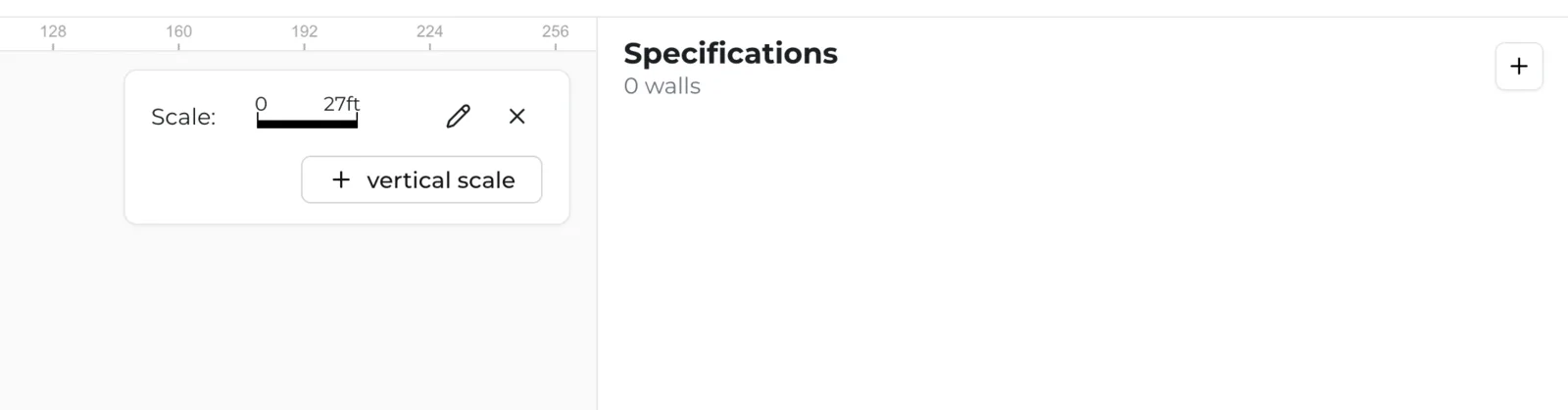
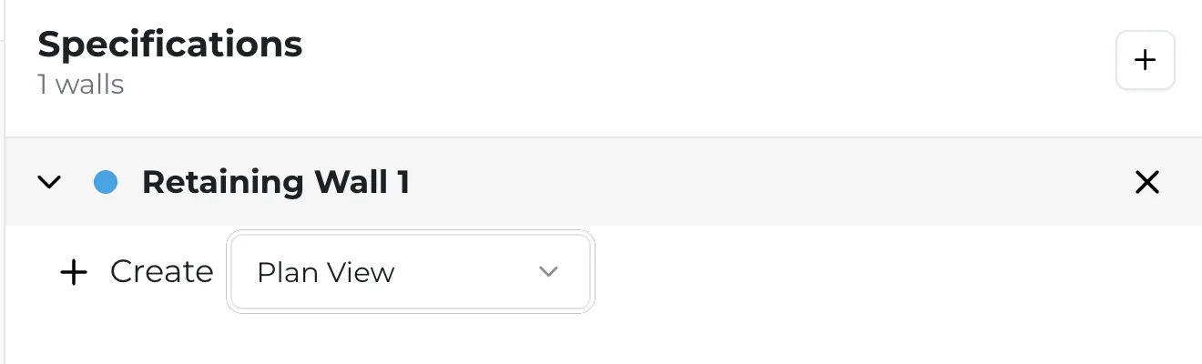
In your new specification, select the Plan View takeoff tool from the dropdown, then click the + button immediately to the left of the word Create to start taking off the wall.
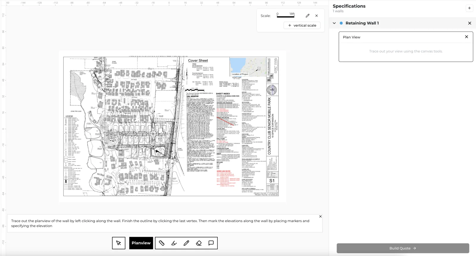
You're ready to take off when the Plan View rectangular component beneath your specification is bordered in black and a black Planview tool appears in the toolbar at the bottom of the screen.
Renaming a wall — you can change the name of any Specification / retaining wall by clicking its name (like "Retaining Wall 1") and typing a new one.
Tracing the wall
A plan view takeoff has two steps:
- Trace the line of the plan view retaining wall to record the horizontal run of the wall, including its bends, corners, and radii.
- Add elevation markers to the trace line to record the elevation data of the wall relative to its run.
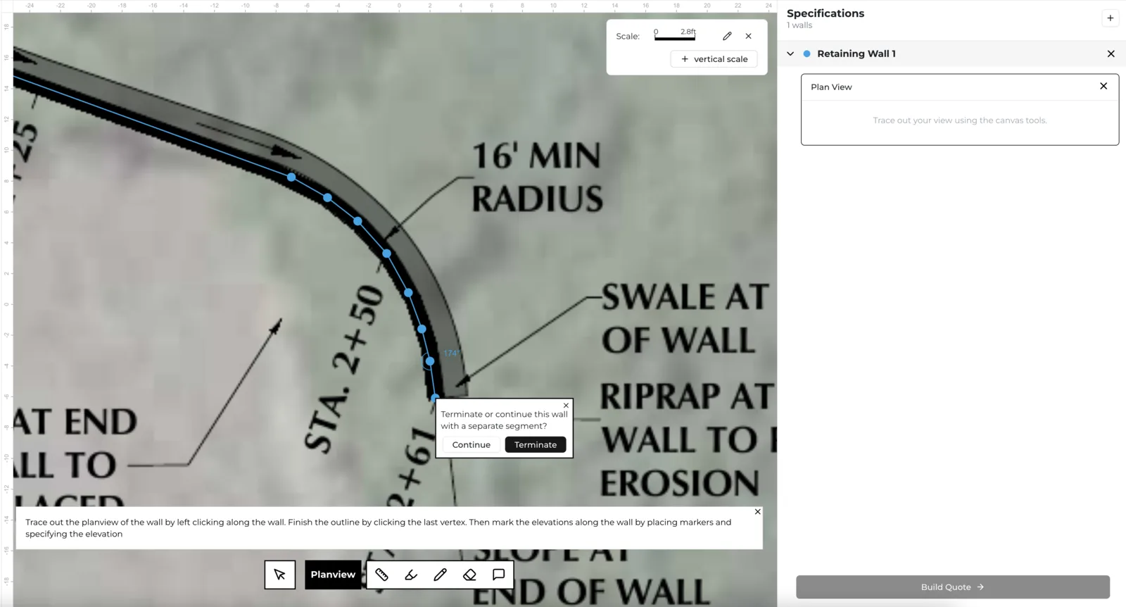
To trace the run, click along the wall to add vertices. Click one end of the wall to add the first vertex, then move your cursor to another point along the wall and click to add a second. Keep adding vertices to follow the line of the wall as best you can. For a hard turn, place a vertex at the corner and continue on. For a radius, place multiple vertices to segment it.
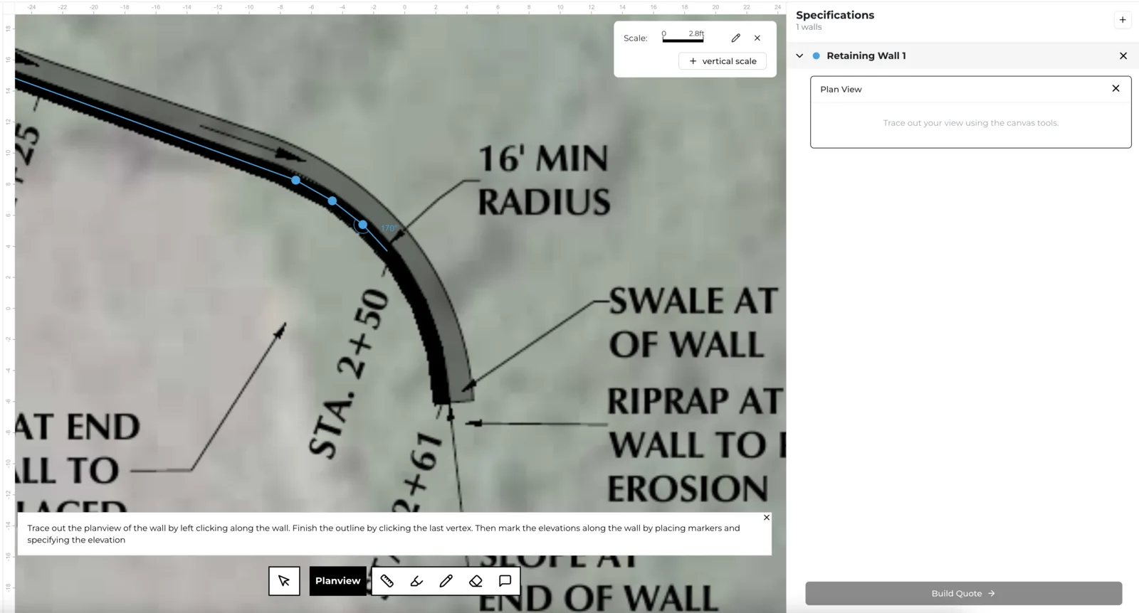
Once you've completed your trace, click your last vertex once more. You'll be prompted: "Terminate or continue this wall with a separate segment?" If you've traced the entire wall, click Terminate. If you've reached a match-line, click Continue.
Continuing with match-lines
If you clicked Continue because you reached a match-line, the tool attaches a match-line to your cursor. Use it as the first vertex of the wall's next segment. If that segment is on a different page, set the scale on that page first by clicking Set Scale — afterwards the match-line re-populates on your cursor and you can carry on. You can use as many match-lines as the wall requires.
Adding elevation markers
If you clicked Terminate because you reached the end of the wall, a small bubble floats alongside the line you traced and follows your cursor. Use it to mark elevations along the wall.
Which side of the wall you place markers on matters. Decide which side is the top of wall and which is the bottom, then place the lower elevations on the bottom-of-wall side and the higher elevations on the top-of-wall side. That's how Struction determines which way the wall faces.
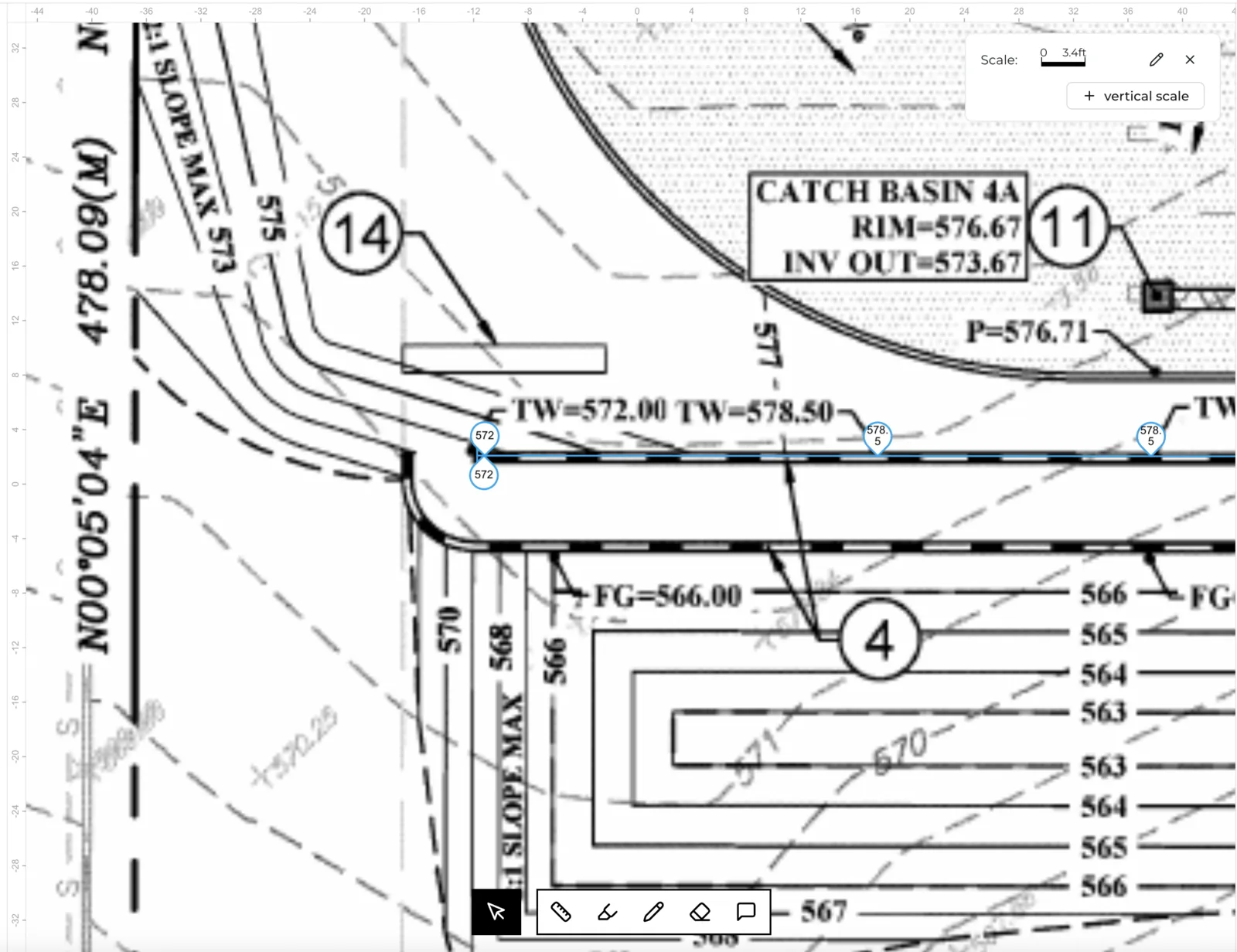
Place markers for every known elevation — the more data, the better. Use the profile view of your takeoff, on the right side of the screen beneath the specification, to check that the elevations you're marking make sense to Struction.
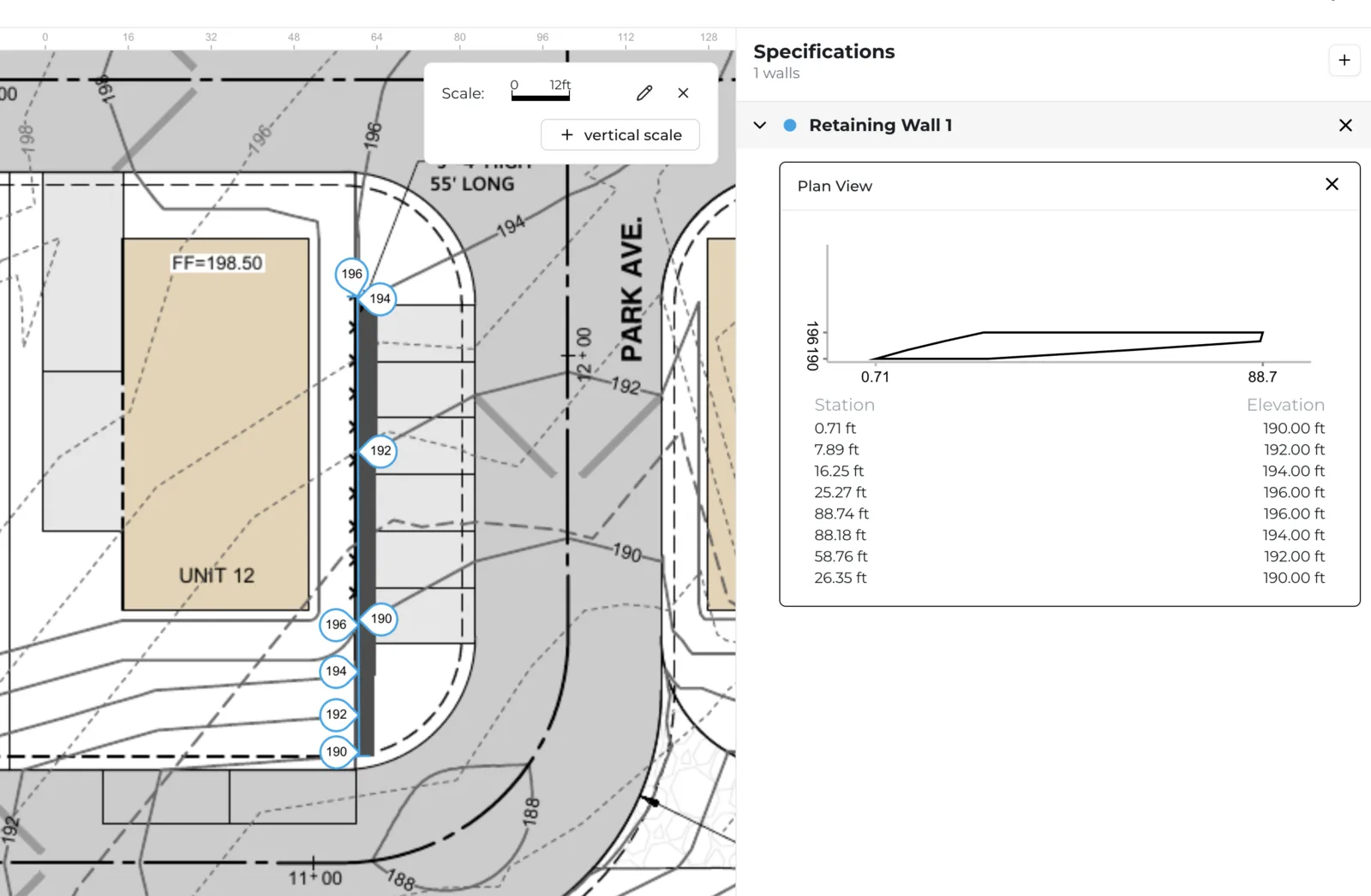
If the profile view looks wonky, more data usually fixes it. You can even add elevations where the drawings don't state one explicitly, as long as you're confident in the value.
When you're done, click the Cursor tool in the toolbar to exit the plan view takeoff tool.

To take off more plan view walls, start again from step one. If your next wall is drawn in elevation view, see Elevation View Takeoff.
More docs
Docs for